This post shows how to build a do it yourself 110 volt soldering station. It is a step by step guide that shows how to convert a regular plug-in soldering iron into a temperature controlled unit.

It is an easy project that is inexpensive to make and requires only basic skills to build. It is made from off the shelf parts that can be obtained from online suppliers plus a few parts from a local hardware store. It is inexpensive to build plus it makes a shop tool that is on par with some commercially available units.
A thermocouple was inserted into the soldering iron at the rear of the heating element and the power cord and AC plug were replaced with a flexible multi-conductor cord and 4-pin DIN connector.
WATCH VIDEO
The controller is a simple circuit made from a dual digital display PID temperature controller plus an SSR (solid state relay). It is housed in a metal instrument enclosure complete with a fuse holder, an on-off switch and a standard IEC power cord.

DIY 110v Soldering Station Wiring Diagram (click for larger view)
A 220 volt unit could also be made in countries that use a 220 volt mains supply. The power input for the PID controller accepts a voltage range of 90v – 260v AC and the SSR supports a voltage range of 24v – 380v AC for switching the soldering iron.
The soldering iron chosen for this project was a Great American Brand 110 volt, 60 watt unit. It has a mica tube heating element and adapts well for this project. Similar inexpensive soldering irons may also be suitable for this modification and are available in different areas under various trade names.

Building The Unit
Most of the parts are shown in the video below and the following table lists each part along with suppliers and links.
WATCH VIDEO
| Item | URL | Qty | My Cost | Note | |
| IL12A Soldering Iron | link | 1 | 6.99 | ||
| Type K Thermocouple, 1 Meter | link | 1 | 1.37 | (5 for 6.85) | |
| Multi Conductor Cord | link | 1 | 5.43 | (2 for 10.86) | |
| RG58 Strain Relief Boot | link | 1 | 0.28 | ||
| 4 Pin DIN Connector, Male | link | 1 | 0.79 | (2 for 1.58) | |
| 4 Pin DIN Socket, Female | link | 1 | 0.80 | (5 for 3.99) | |
| PID Temperature Controller | link | 1 | 19.69 | ||
| Solid State Relay SSR 25DA | link | 1 | 2.42 | ||
| Metal Enclosure Case, E1 | link | 1 | 7.25 | ||
| SPST Rocker Switch, 120V, 15A | link | 1 | 0.72 | (5 for 3.58) | |
| IEC Power Receptacle | link | 1 | 1.25 | ||
| 3AG Panel Mount Fuse Holder | link | 1 | 0.90 | ||
| 6′ IEC Power Cord | link | 1 | 3.25 | ||
| Soldering Stand | link | 1 | 4.00 | ||
| Total | 55.14 |
Part I: Modifying The Soldering Iron
Modifying the soldering iron involves installing a thermocouple and replacing the power cord and AC plug with a multi-conductor cord and 4 pin DIN connector.
Below is a photo of the soldering iron before modification.

Disassembly is straightforward. Two screws hold the two halves of the handle (shown in photo below) and three smaller screws hold the metal parts to a black plastic collar.

Replacing the Power Cord
An RG58 strain relief boot is fitted to the soldering iron handle. A small piece is trimmed off the large end with a precision utility knife. It fits neatly into a recessed area of the handle. A new, unaltered RG58 strain relief boot is shown next to the modified one with the trimmed off piece just below.

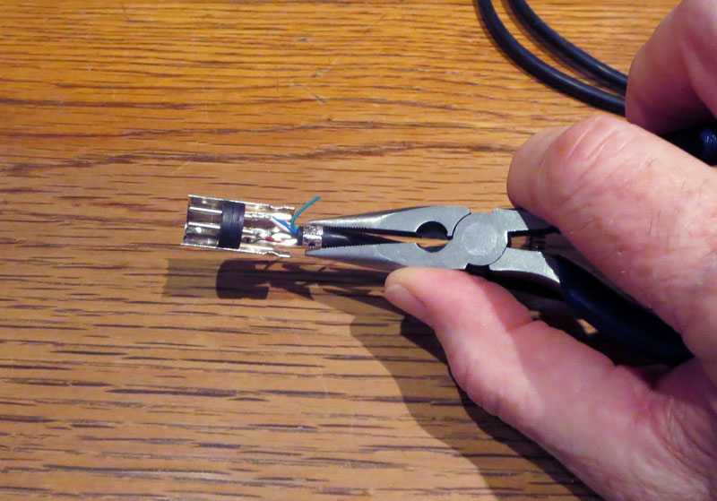
The connections between the power cord and heating element leads are secured with aluminum crimping in line connectors.

The connectors were removed by using a pair of long nose pliers and by squeezing the original crimped connectors from the sides. The leads remain intact and undamaged.

This soldering iron also has a round plate (shown in photo above). This round plate mates between the plastic collar and another round plate retainer for the metal enclosure tube that covers the heating element and soldering tip.
A length of five conductor cord replaces the power cord. This was cut to match the length of the original power cord (a little over 4 feet in length).

Shown below is the 4 pin male DIN connector. A small metal retaining tab is visible through an opening on the plastic part.

The connector is disassembled by pressing down on the metal tab with a small screwdriver. This will disengage the metal parts from the plastic cover and allow the unit to be disassembled.

Shown below is a diagram of the pinout. The pin numbers are standard for a 4 pin DIN connector. The assignments were arbitrary but follow the general layout for similar soldering irons using a 5 PIN DIN connector as in this previous post.

4 Pin DIN Connector Male Pinout
Sections of the outer silicone jacket were trimmed from the ends of the cord and a small length from each conductor was stripped. The pins for the male connector were soldered to four of the five conductors. The green conductor, normally reserved for a ground connection, was not connected because this soldering iron has no ground wire.

A female socket was plugged into the male pins during the soldering operation (see photo above). This was done to help maintain alignment in case the plastic support for the pins experienced distortion due to heat.
The red and black conductors were soldered to the thermocouple positive and negative pins, respectively. Red and black are usually used for positive and negative DC wires, but in hindsight I should have used the red and blue wires for the thermocouple conductors. This would have allowed the black and white conductors for the AC hot and neutral.
After soldering, the connector was crimped to the the cord using a pair of long nose pliers.
Thread the opposite end of the cord through the RG58 strain relief boot prepared in an earlier step. Note the stripped wires in the photo below.

Attach an 8 inch cable tie to the end of the cord. Make sure the cable tie is pulled tight so it won’t slip off the end of the cord. It should fit into the space in the handle like in the photo below.

Trim away the excess cable tie so it is flush like in the photo below. You may have to file down the corners of the end of the cable tie a little bit so both halves of the handle fit together without any gaps.

Both halves of the handle are temporarily assembled with the two screws to check the fit of the cord and cable tie.
Enlarge The Round Plate Center Hole
The center hole of the round plate has to be enlarged to allow room for the thermocouple plus the heating element leads. Below is a photo of some of the hand tools needed:

A taper reamer and a round file were used to enlarge the hole. Locking pliers were used to hold the workpiece.

The hole diameter was checked with a digital caliper. This hole measured at 9.75 mm, but the size can be rounded off to 10 mm. It has to be large enough to clear the thermocouple plus the heating element leads plus a small cable tie. This hole was just big enough with a little wiggling.

Preparing and Installing The Thermocouple
A thermocouple has to be prepared either from a commercially available one or from thermocouple wire (two wire cable). The photo below shows a commercially available thermocouple that is rated for a temperature range of -50°C to 700°C.

Bear in mind that the thermocouple has to be able to read the full range of temperature for a soldering iron. This soldering iron was checked with a tip thermometer at approximately 454°C. Some soldering irons reach 585°C or more. That’s why the proper thermocouple wire selection is important.
This is a one meter thermocouple and the project only requires a few inches. There is plenty of wire left over after it is trimmed and more units can be made from the remaining wire, but the wire ends should be spot welded. I have had bad luck with unwelded wires that were just twisted together because the readings were unstable.
If there is no access to a proper thermocouple spot welder, the thermocouple can be spot welded with a 12 volt car battery, a set of jumper cables, a claw hammer and a pair of long nose pliers. Please see this post for details.
The photo below shows the thermocouple plus the mica tube heating element. More info on this type of heating element can be found at this post. The thermocouple is trimmed approximately to the same length as the heating element leads. The spot welded tip of the thermocouple needs to be located at the rear opening of the heating element.

Please note the thermocouple fiberglass insulation. Each individual wire is insulated plus the cable is wrapped with an outer layer of fiberglass insulation. I prefer fiberglass over plastic insulation. It is very heat resistant.
Also please note the black heat shrink tube on the end of the thermocouple in the photo above. If the thermocouple is to be made from wire, then the end should be finished with a piece of heat shrink tube like the photo above.
The thermocouple was tested with a K Type thermometer to ensure proper functionality before it was installed in the soldering iron. The insulation on the positive lead has a red stripe and the insulation on the negative lead has a blue stripe.

Cut a length of 4mm ID fiberglass sleeve (rated at 600°C) plus lengths of 1/8 in and 3/16 in inch heat shrink tube similar to the photo below. The pieces can’t be too long because there isn’t much room on the thermocouple.

Position the 3/16 in piece of heat shrink tube over the fiberglass sleeve so it overlaps about 50% like the photo below. Shrink it down with a heat gun. Note the position of the utility knife blade. It is pointing to the location of the spot welded tip of the thermocouple, recessed about 1/8 in inside the end of the fiberglass sleeve.

Next, shrink down the 1/8 in piece of heat shrink tube over the 3/16 in piece. This is what holds the fiberglass sleeve to the thermocouple. The thermocouple is now ready to install.

Position the fiberglass sleeve slightly inside the rear of the heating element and tie the thermocouple and heating element leads together with a small cable tie. Trim the length of the excess cable tie flush. Alow adequate distance from the heat source to prevent burning or damage to the cable tie.

The position of the thermocouple at the rear of the heating element will probably need to be adjusted. The amount of adjustment will depend on the temperature difference between the thermocouple and the soldering iron tip.
Adjust the position in or out depending on the temperature difference. Generally, the thermocouple should be positioned closer towards the heating element to increase the temperature reading or farther away to decrease the temperature reading. Use a test rig similar to the one described below.
Thread the round plate that was modified in an earlier step plus the black plastic collar over the thermocouple and heating element leads like the photo below.

Slip the metal enclosure tube and round retainer plate over the heating element and align the screw holes in the black plastic collar with the holes in the round plates. Fasten with the screws previously removed. Position the black plastic collar into one of handle halves like the photo below.

Cut lengths of heat shrink tube and thread them over each power cord lead like the photo above (click to enlarge).
Connect the power cord and heating element leads and twist them together. Do the same for the thermocouple leads. Then slide the heat shrink tube over each connection like the photo below. Pay close attention to the connections.

Use a continuity tester to check the connections. Plug the male DIN connector into a female DIN socket and check the continuity of each conductor. Make sure that the AC pins connect to the heating element and that the positive and negative thermocouple pins connect to the positive and negative leads of the thermocouple.
Use a heat gun to shrink each piece of heat shrink tube. Be careful not to damage the plastic handle with heat. When using the heat gun around plastic parts, it is a good idea to use a piece of cardboard as a shield to deflect heat away and to prevent their exposure to heat. The cardboard backing from an ordinary legal pad like the one in the above photo was used for this project.
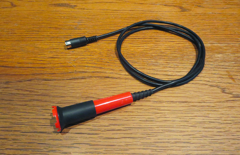
Reassemble the soldering iron when done. The photo below shows the soldering iron after modifications.

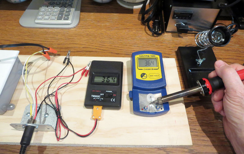
Below is a photo of a soldering iron test rig with a dimmer control. Details for making a dimmer controller can be found in this previous post. Plug in the soldering iron and connect the K type thermometer to the thermocouple pins on the back of the female DIN socket.

Adjust the dimmer control to about half way and allow the soldering iron to heat up. The thermometer will display the temperature of the thermocouple from inside the soldering iron. Use a soldering iron tip thermometer to compare with the thermocouple reading.
Adjust the position of the thermocouple as needed, raising or lowering the temperature reading as needed until it matches the soldering iron temperature as close as you can get it. The photo below shows that the soldering iron tip and the thermocouple temperature are both 364°C.
Part II: Building The Controller
Building the controller involves arranging the components in the enclosure, drilling holes and making the cutouts for the parts, mounting the components and then wiring and testing the unit.
Enclosure Layout and Mounting Holes
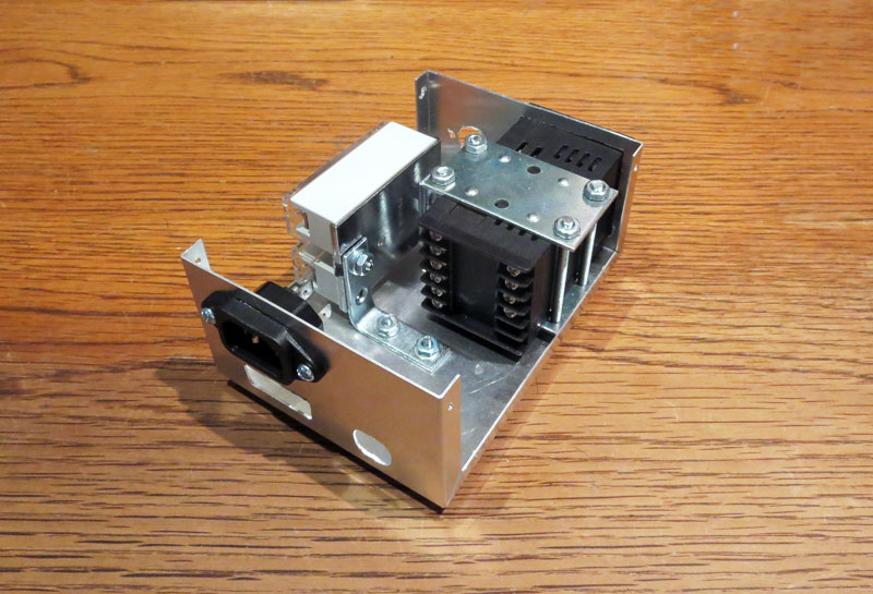
The photo below is a left rear view of the enclosure layout. The arrangement of the IEC power receptacle, SPST switch and fuse holder can be seen on the rear panel plus the SSR will be mounted vertically with 1 1/2 inch corner braces.

Note: There is no SSR heat sink in this unit. There was not enough space for a heat sink in this enclosure, but I did not experience any heat whatsoever from the SSR with this circuit.
Another view of how all the parts are arranged can be seen in the photo below.

Measurements were taken and a layout was sketched for each panel. Using the sketch as a guide, the markings for the cutouts were drawn on the each panel. The layout of the front panel can be seen in the photo below.

The aluminum panels are covered with a translucent blue protective plastic which was peeled off after all the drilling, cutting and shaping has been completed.
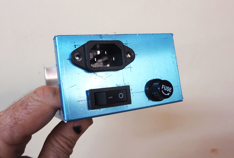
The layout of the rear panel cutouts can be seen in the photo below. Measure carefully before drilling or cutting.

A 1/8 inch drill bit is used with a power drill to make the first holes. The plan was to start small and enlarge holes as needed.

The photo below shows the rear panel after drilling with the 1/8 inch drill bit.

Some of the holes are enlarged before using a round file or a nibbler.

Below is a photo of the rear panel showing the completed cutouts. The switch was only partially mounted into the cutout to avoid snapping it into position.

Parts were checked for fit in each cutout in a view of the rear panel below.
A similar view of the front panel shows the PID controller and DIN socket being checked for fit.

A view of the bottom panel shows the arrangement of the mounting holes that were drilled for the SSR and the PID controller.

Holes were also drilled for the enclosure bracing screws on the upper left and right corners of the side panels. These were needed for extra support when plugging in the power cord and for pressing the buttons on the controller.

Mounting The Parts
The SSR was mounted first. I used 6-32 x 1/2 inch machine screws to mount the braces to the SSR and 6-32 x 3/8 inch screws to mount the unit to the base.

I used 8-32 x 2 1/2 inch machine screws to mount the PID controller, but they had to be trimmed to a length of 2 1/4 inches.
The mounting braces for the PID controller were checked for fit in the photo above. I used 2 1/2 in “mending braces” that I bought at a local hardware store. The PID controller does come with its own set of mounting brackets but there was not enough clearance to use them in this enclosure.
Controller Wiring
Leads were cut and soldered to the female DIN socket, then heat shrink tube was used to cover the soldered connections.

Leads were soldered to the fuse holder and flat crimp terminals were installed on the ends. Heat shrink tube was used to cover exposed connections.

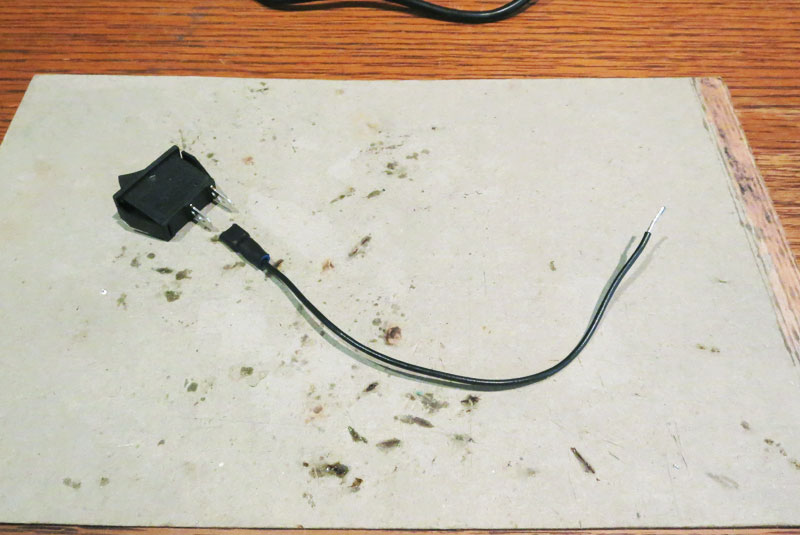
The photo below shows the wire for the switch that supplies AC power to the PID controller.
Black, white and green leads were prepared for the IEC power receptacle. A ring terminal was later crimped onto the end of the green (ground) wire. It would be fastened to one of the machine screws on the base as a ground.

A final stage of wiring is shown in the photo below. All that remained was to wire up the PID controller. Click the photo for a larger view to see more detail. The ground wire can be seen with a ring terminal that fastens to one of the SSR mounting braces.
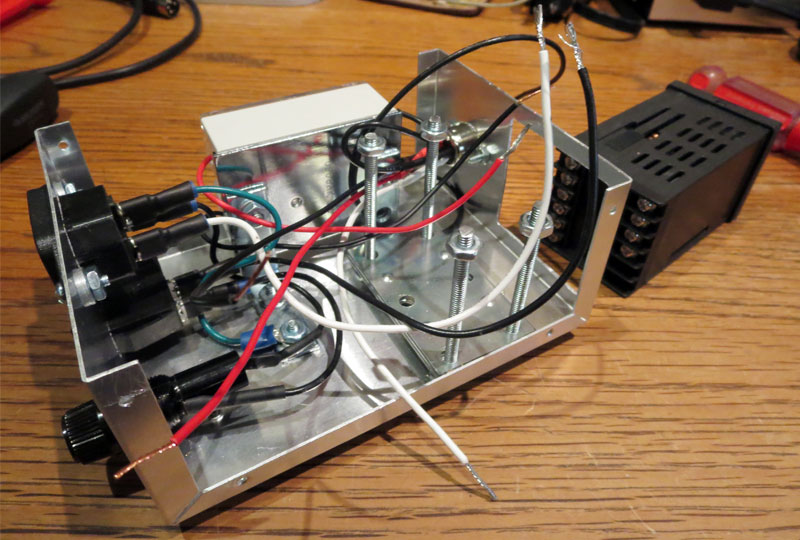
The hot and neutral AC wires were connected to the PID terminals in the photo below. After that, the positive and negative wires to the SSR were connected to the PID controller.

Finally, the positive and negative wires from the thermocouple (pins 1 and 2 on the female DIN socket) were connected to the PID controller.
The wiring was complete and the next step was to do continuity checks of the wiring. A copy of the wiring diagram was used and each connection was checked one by one to make sure the wiring was correct.

Above chassis view left and below chassis view right.

The soldering iron was plugged in and the unit was powered up. The unit had to be to tuned and some settings had to be changed in the PID controller. See the links below to the support videos for more details on how to adjust the controller settings.

Auto Tuning vs. Manual Tuning
The PID controller has an auto tuning function. Normally auto tuning works pretty well, but this unit needed some manual tuning after it was auto tuned. For some reason the “P” (Proportional) value would come up short and the temperature would undershoot the set point by a few degrees.
I auto-tuned twice, once from a hot start and once from a cold start. Auto-tuning from a cold start was better. The result was more optimum “I” (Integral) and “D” (Derivative) settings. All I did was restore the factory default “P” value to 3.00 and the unit worked like a charm after that.
Support Videos For the 110v Soldering Station
DIY 110v Soldering Station: PID Controller Settings
DIY 110v Soldering Station: Temperature Setting

Found your post at dangerousprototypes. Great job with this DIY soldering station.
Thanks. I appreciate it.
Can this work with 230v 50Hz power supply..if not,what changes has to be made??
Yes, this should work fine. Just double check the temperature controller input power supply specs. I’m pretty sure it supports this. – M.D.
Hi, thank you for sharing. I like this project ’cause it is very simple to implement and appears to be very reliable. I have read all your posts on pcbsmoke. The only problem is to find an iron like the one you have used, here in Italy where I live, and of an acceptable quality (it does not make sense to build a reliable controller if using a bad iron/tips,imho). Also, I’m facing a problem with my Velleman VTSSC50N soldering station (a really junk chinese station!). So my questions are:
– what 220V/60W iron has same shape and, overall, room for thermocouple?
– is the AGPtek PID Temperature Controller reliable? I have found an Omron (model E5CJ-Q2HB http://media.digikey.com/pdf/Data%20Sheets/Omron%20PDFs/E5xJ.pdf) working with K type thermocouple at 40 $. Is it worth?
Furthermore,
– I already have a brand new 24V Hakko 907 iron “chinese clone” with I don’t know if with thermistor or thermocouple, which I have read working goos “almost” like the genuine one. Though, is it possible to set the components to work with it (or any other 24V stylus)?
Thank you for any help.
Ross,
Re: finding an iron in Italy … 220V/60W iron has same shape and, overall, room for thermocouple:
I have seen some YouTube videos and blog posts with a similar iron with a white handle with yellow or blue plastic sleeve. One I think was in Spain and the others were I think from an Eastern European country or Russia. I am not not sure. They did not mention any brand name but I think one post mentioned that it was a cheap iron.
Examples:
http://tinyurl.com/n4wbxwg
http://tinyurl.com/hxxvevo
I think this type of iron is very common in Europe. I think the important things are adequate power (60w not 30w) plus available tips. Most come with cone tip. I prefer chisel tips. The mica tube heating element like this project is also crucial, but is very common.
In the USA I have found a 110v ZD-99 replacement iron for about $4.95 USD. I think it is good for this project. I plan to post details, but it will take some time as currently I am very busy. I believe a 220v version of this iron is available in Europe:
http://tinyurl.com/zc7jyxs
Re: AGPtek Controller:
The one I used from Amazon.com seems pretty reliable. Just make sure it is a TA4-SNR not TA4-RNR. RNR has a built in relay and will not connect to SSR.
Re: Omron E5CJ-Q2HB Controller:
I don’t have any experience with this one so I don’t know.
Re: 24V Hakko 907 iron “chinese clone” … thermistor or thermocouple
I believe that is the best iron for a homemade unit. It uses a PTC thermistor (positive temperature coefficient).
Re: Though, is it possible to set the components to work with it (or any other 24V stylus)?
It is possible to use that iron and make a circuit similar to this:
http://tinyurl.com/jnbu75m
Many temperature controllers like the ones in these projects will support PT100. PT100 is also PTC but the problem is that the resistance values of the PTC sensor in these Hakko clones are on a different scale altogether than PT100. You would have to adapt the sensor output to match the PT100 values. This can be done with a micro controller but it requires some programming and a custom circuit board. Maybe it can be done with an Arduino module (?) I also have a Hakko clone and I plan to make a 24v soldering station for it but I am not sure yet if I want to adapt it to one of these existing temperature controllers or build the whole circuit from scratch. I am still thinking about it.
Good luck with your project.
Hello Mike,
the project is almost at its end. I have got an Omron E5CJ-Q2 on eBay and works very fine. I have followed your suggestion and got a 40A SSR. At this moment the prototype works with a “Hakko” clone handle 50W 24V (very nice for the money) and I am very happy. Thank you for your very interesting articles and for having led me to try. Best regards.
Mike,
thank you for replying. I’ll take care of your suggestions.
Best regards.
Hi Mike,
going ahead with the project.
Can I use a 24V DC power supply instead of an AC one to power the 24V stylus?
Thank you.
Yes I believe that should work fine.
Hello Mike,
the PID controlled soldering station project is at the end. Works very well as expected. Great tool. Thank you.
Thanks for the feedback. It’s nice to hear you had a good result.
Thanks.
Hi, do you know if there is a chisel tip model for that solder, or the solomon chisel tips will work with it?
Thanks
hi
hi, what amperage is the fuser used, also the solomon or vellerman tips can work with this solder, i want to put a chisel tip on it.
The fuse is 1/2 amp (500 mA) for 110v AC supply. The supplier of this IL12A soldering iron does not offer any replacement tips but I think that the 28020 Fahrenheit Analogue Variable Temperature Soldering Station in the EU uses the same tips. Some chisel tips are still available in the EU for this unit: http://www.ebay.ie/itm/271263343205. I believe Tenma also made chisel tips that would work. Tenma chisel tips 21-790 and 21-7971 used to be available from from mcmelectronics.com but were discontinued awhile back. I don’t think Solomon or Velleman tips will work with this soldering iron but I am not sure. In the US I bought a 110v 58w replacement iron for the ZD-99 from mpja.com for 4.95 here: http://www.mpja.com/Mini-Solder-Station-15860-TL-ZD-99-Replacement-Handle/productinfo/15861+TL. Chisel tips for this iron here: http://www.mpja.com/ZD-99-Solder-Station/products/461/. I plan to modify this ZD-99 iron to use with this controller.
Im sorry been insistent, but im really insterested in this proyect.
Do you have any link for buy the “4mm ID fiberglass sleeve (rated at 600°C)”, also; if the k type probe can measure up to 700ºC; the outer sleeve should not withstand that temperature for been reused in covering the tip?
The link for the fiberglass sleeve: http://www.aliexpress.com/item/4-3mm-10M-lot-UL-Certified-white-high-temperature-Glass-fiber-braided-sleeve-for-protection-cable/32225334673.html. Re: “if the k type probe can measure up to 700ºC; the outer sleeve should not withstand that temperature”: I checked the temperature of a couple of 60w soldering irons. The max temp for the IL12A unit for this project was 430 degrees C. Even the hottest iron I have with a ceramic heater was max 557 degrees C. So even though the thermocouple is good for up to 700 degrees, the iron will never go past 600 or reach 700. Check the temperature of your iron first to be sure.
[…] « DIY 110v Temperature Controlled Soldering Station […]
Hi, I just found your article through your YouTube videos and this is a project that I’m very much interested in doing myself.
One thing that I wondered is about the current to power the soldering iron. Aren’t those cables that supply it too thin for this? I’m basing this assumption on the 15A fuse. Is it safe to use such a thin wire on such a high current?
I’m using a 1/2 amp fuse. With a 60 watt iron it should draw between .50 to .55 amps between 120 to 110 volts. I haven’t blown a fuse yet. The multi conductor cord used in this project was made to be used with a 24v soldering iron. A 24v 60 watt soldering iron would draw 2.5 amps so it should work fine for this 110 volt soldering iron.
My mistake then… somewhere I read a current of 15 A. Should’ve read more carefully then. Indeed a 60W at 120V would never draw such a high current.
I’m eager to get all the materials and start my own iron. I specially liked your article on a simple spot weld! Hopefully I’ll try it soon! Thanks for the answer!!
This is a wonderful article. Most useful! Thank you for being so thurough, and generous with your time.
I built this as a controller for a branding iron. I needed a more stable temperature for a more consistent brand. Your project was the first I’ve attempted of its kind, and thanks to a great job of producing your video, my attempt was perfectly suited to the task! Very cool gaget, and a fun side venture for my hobbies/Etsy buisness. Thank you so much for sharing your time and efforts.